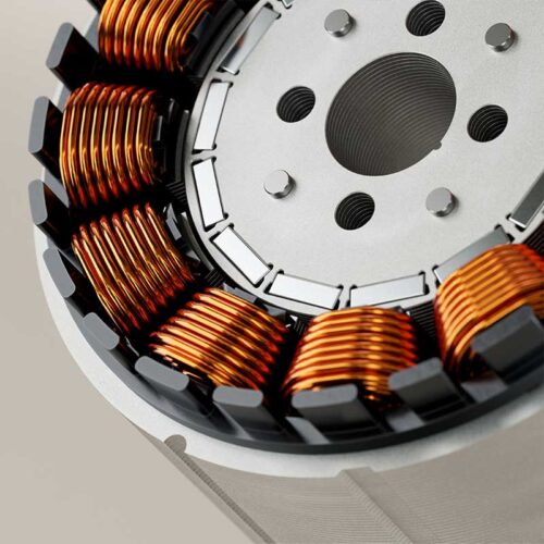

Der IR-F 52 kombiniert Leistung mit einer kompakten Bauweise und hat einen Außendurchmesser von 52 mm (2,05 Zoll). Er bietet Spitzendrehmomentwerte von 0,49 Nm bis 1,44 Nm
Selecting the right frameless inrunner PMSM torque motor is essential for achieving the desired performance, efficiency, and reliability of your machine. Whether you are designing a robotic joint, a high tech handling system, medical device, or industrial automation platform, choosing the correct motor requires more than simply looking at torque values.
At Magnetic Innovations, we help engineers select direct drive motors based on application requirements, available installation space, performance targets, and environmental conditions. Our Serie IR-F of frameless inrunner PMSM motors covers a wide range of applications, from compact precision systems to demanding industrial machinery.
Step 1: Define the Required Torque
Torque is typically the starting point for motor selection.
When evaluating an inrunner PMSM Torque Motor, both continuous torque and peak torque should be specified. Continuous torque represents the torque required during normal operation, while peak torque defines the short-duration torque needed during acceleration, deceleration, or temporary overload conditions.
For example:
- Continuous torque: 4 Nm
- Peak torque: 8 Nm for 2 seconds
Choosing a motor based solely on peak torque may lead to overheating, while selecting only on continuous torque may limit machine performance.
Typical IR-F Inrunner PMSM Torque Motor Ranges
| Series | Continuous Torque Range | Peak Torque Range | Outer Diameter |
|---|---|---|---|
| IR-F 52 | 0.22 – 0.97 Nm | 0.49 – 1.44 Nm | 52 mm |
| IR-F 85 | 1.3 – 6.4 Nm | 3.5 – 7.9 Nm | 85 mm |
| IR-F 170 | 11.6 – 56.2 Nm | 31 – 70 Nm | 170 mm |
What if I Don’t Know the Required Torque?
Many engineers are familiar with specifying motor power (kW) and speed (rpm), but not necessarily torque. This is especially common when replacing a conventional motor and gearbox combination with a direct drive solution.
Torque is the rotational force produced by the motor and is often the most important parameter when selecting a frameless PMSM torque motor. In many applications, the required torque can be calculated from the existing system’s power and speed requirements.
Converting Power and Speed to Torque
When replacing a traditional motor and gearbox, the required torque can often be estimated from the available power and operating speed.
Torque (Nm) = (9550 × Power (kW)) ÷ Speed (rpm)
For example, a 1 kW motor operating at 2,000 rpm generates approximately 4.8 Nm of torque (Torque = (9550 × 1) / 2000 = 4.8 Nm.)
If the required torque is unknown, our engineering team can help determine the motor requirements based on your application, load characteristics, duty cycle, and performance targets.


Step 2: Determine Required Speed
Maximum operating speed is another critical selection parameter.
A robotic joint may only require a few hundred rpm, while indexing systems or rotary stages may require significantly higher rotational speeds.
Engineers should define:
- Maximum speed (rpm)
- Continuous operating speed
- Required workpoint
The combination of speed and torque determines the mechanical power requirement of the application.
Step 3: Calculate Mechanical Power
Understanding the required mechanical power helps engineers estimate the motor size, thermal performance, and cooling requirements for the application. In general, applications that require both high torque and high speed will need a larger motor and may require active cooling.
Mechanical power can be calculated using: P = Tω
Where:
- P = Mechanical Power (W)
- T = Torque (Nm)
- ω = Angular velocity (rad/s)
Step 4: Check Available Installation Space
One of the biggest advantages of frameless direct drive motors is their ability to integrate directly into the machine structure.
Before selecting a motor, determine:
- Available outer diameter
- Available motor length
- Maximum stator mass
- Maximum rotor mass
These parameters are also part of our frameless motor specification process.
Step 5: Consider Cooling Requirements
Heat generation directly affects motor performance and lifetime.
When selecting a torque motor, engineers should consider:
- Maximum allowable power dissipation
- Operating duty cycle
- Ambient temperature
- Cooling method
Typical cooling options include natural convection, forced air cooling and water cooling. Applications requiring high continuous torque may benefit from active cooling solutions to maximize performance.
Why Choose an Inrunner PMSM Torque Motor?
Unlike conventional housed motors, a frameless motor consists only of the rotor and stator. The motor is designed to be integrated directly into the machine structure, allowing engineers to optimize performance, packaging, and system design.
Because frameless motors do not include bearings, housing, shaft, feedback devices, or cooling systems, these elements must be incorporated into the final machine design. While this requires additional engineering effort, it provides maximum flexibility and enables highly compact, high-performance direct drive solutions.
Advantages Frameless Inrunner Torque Motor
Compared to conventional geared systems, frameless direct drive motors offer:
- Higher positioning accuracy
- No gearbox backlash
- Lower maintenance requirements
- Higher efficiency
- Compact machine integration
- Improved dynamic response
- Increased system reliability
These advantages make inrunner PMSM torque motors a preferred solution for robotics, high tech equipment, medical devices, and advanced automation systems.
Need Help Selecting the Right Motor?
Every application is unique. If you are unsure which motor series best fits your requirements, our engineering team can help evaluate torque, speed, thermal performance, installation constraints, and environmental conditions to recommend the most suitable solution.
Available Magnetic Innovations Inrunner PMSM Torque Motor Solutions
The Magnetic Innovations IR-F series covers a wide performance range, from compact precision motion systems to demanding industrial automation applications. Available in three outer diameter and multiple stack heights, the IR-F series enables engineers to optimize torque, speed, thermal performance and installation space for their specific application.
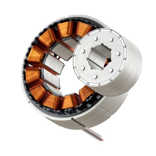
IR-F 85
Die perfekte Balance zwischen Leistung und Präzision mit einem Außendurchmesser von 85 mm (3,35 Zoll). Die Motoren der IR-F 85-Serie liefern ein beachtliches Spitzendrehmoment von 3,5 Nm bis 7,9 Nm.
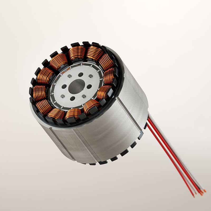
IR-F 170
Die IR-F 170-Serie ist mit einem Außendurchmesser von 170 mm (6,69 Zoll) für anspruchsvolle Industrieanwendungen konzipiert und bietet ein maximales Drehmoment von 31 Nm bis 70 Nm.

Ebenfalls erhältlich: Outrunner-Torquemotoren
Für Anwendungen, die ein höheres Drehmoment bei niedrigeren Drehzahlen erfordern, bieten wir auch Außenläufer-Torquemotoren an. Diese Motoren liefern außergewöhnliche Leistung, da der Rotor außerhalb des Stators positioniert ist.
Dieses Design ermöglicht eine höhere Drehmomentdichte, wodurch Außenläufer ideal für Anwendungen sind, die ein hohes Drehmoment auf engstem Raum erfordern. Außenläufermotoren eignen sich besonders für Branchen, in denen ein Betrieb mit niedriger Drehzahl und hohem Drehmoment entscheidend ist.
Unsere MI-F-Outrunner-Torquemotorenserie ist in vier Baugrößen (40 mm, 110 mm, 250 mm und 485 mm) erhältlich, jeweils in drei Höhen (25 mm, 50 mm und 75 mm), mit einem kontinuierlichen Drehmoment von 0,97 Nm bis 1207 Nm.
Kontaktieren Sie unser Support Team
Wenn Sie ein Angebot anfordern möchten, eine Frage zu unseren Produkten haben oder wissen möchten was wir speziell für Sie tun können, kontaktieren Sie uns bitte. Wir werden so schnell wie möglich antworten.